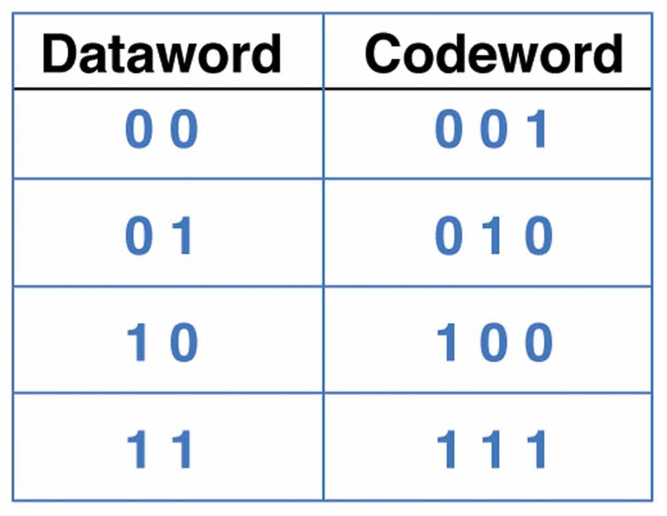
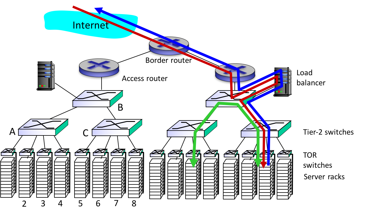
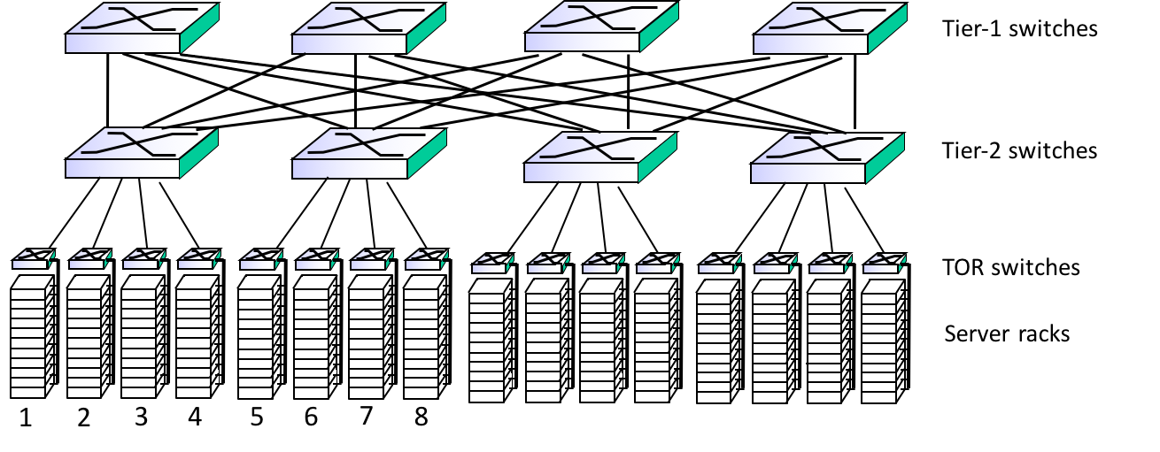
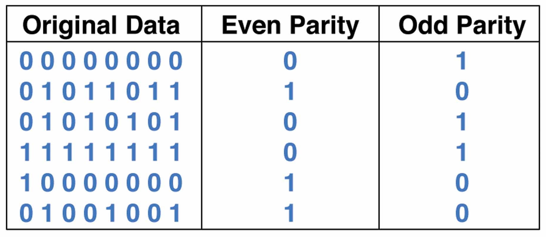
Parity Bits
- simplest form of error detection involves adding a parity bit to each block (e.g., byte) of data bits
- the sender computes an additional bit based on the given d data bits and transmits this as bit d+1
- the receiver performs the same computation and verifies that the parity bits agree
- this ensures that a one-bit alteration can be detected
- parity can be even or odd
- for even (odd) parity, the sender sets the parity bit so that the total number
of 1 bits is even (odd):
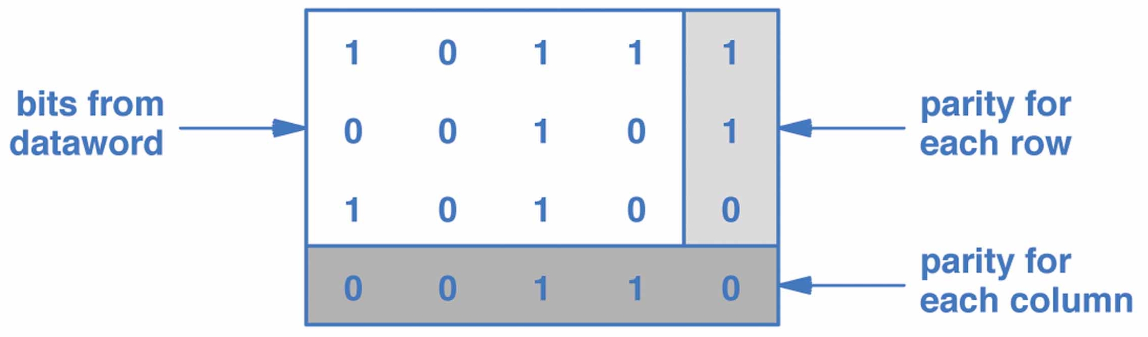
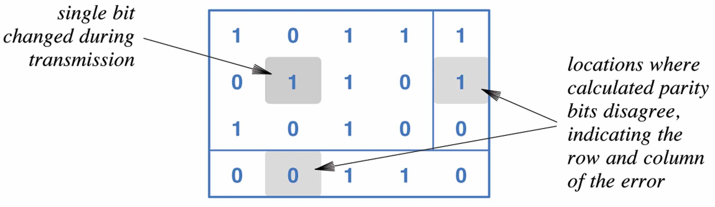
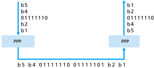
- errors in fact often happen in "bursts", so simple parity checks are usually not enough